by Sean Norris, GE Vernova Grid Automation, UK, Maman Ahmad Khan, Douglas Wilson and Priyank Shah, GE Vernova, UK, and Devinda Perera and Hugo Klingenberg, ElectraNet, Australia
South Australia faces unique challenges in maintaining grid stability due to its high penetration of renewable energy and significant variability in regional inertia. Significant quantities of the states has have been replaced with renewables. It is connected to neighbouring states by way of two AC interconnectors, however these can also bring their own challenges when it comes to grid management and how to protect the system against interconnector issues. These dual AC interconnector systems, link the state to both Victoria and New South Wales. While the dual AC interconnectors improve overall system security, they introduce risks, particularly during non-credible loss events involving either the Heywood Interconnector (HIC) or the South Australia-New South Wales Interconnector (SNI).
Under high power transfer conditions, such events can lead to transient instability of the remaining interconnector, potentially isolating South Australia from the National Electricity Market (NEM). To address these risks, a South Australia Interconnector Trip Remedial Action Scheme (SAIT RAS) was developed as a hybrid protection scheme, integrating both an Event-Driven Component (EDC) and a Response-Driven Component (RDC). The EDC is designed to monitor specific event-based scenarios, such as single- and double-circuit outages on interconnector paths. By leveraging Line End Open (LEO) conditions, it can quickly detect a weakening interconnector path (single circuit outage) or a complete interconnector trip (double circuit outage). This targeted detection enables rapid remedial actions to prevent cascading failures, ensuring robust protection for predictable and well-defined events.
The RDC extends the functionality of the scheme by addressing complex and dynamic disturbances. Using synchrophasor-based wide-area measurements, it monitors real-time system stress indicators such as angular separation, frequency changes, and power imbalance. The RDC employs three key detection criteria: angle and frequency differences to identify divergence between grid regions and assess synchronism, power imbalance detection to measure generation and load imbalances early during transient events by combining inertia, frequency gradient, and power exchange information, and area frequency and Rate of Change of Frequency (ROCOF) to differentiate between disturbances originating within South Australia and those outside, ensuring targeted responses. Triggered responses from the RDC now include a combination of rapid adjustments using grid-scale Battery Energy Storage Systems (BESS), BESS control for active power reduction or increase, and fast generator or load shedding to stabilize the system under extreme conditions. The inclusion of BESSs as part of the response mechanism adds further flexibility and robustness, allowing the system to adapt more effectively to a wide range of scenarios, even those involving multiple sequential disturbances.
The integration of the EDC and RDC within SAIT RAS enhances the management of South Australia’s grid, contributing to a more robust and efficient system. This hybrid approach combines the advantages of event-based detection with dynamic response capabilities to ensure both speed and adaptability in addressing grid disturbances. The EDC ensures specific and immediate responses to well-defined events, while the RDC offers adaptability to handle unforeseen and complex scenarios. This dual-layered approach addresses the risks associated with dual AC interconnector configurations, including large-scale disturbances amplified by distributed energy resource (DER) disconnections due to rapid regional frequency changes.
The principles applied in SAIT RAS are not only tailored for South Australia but are also generally applicable to other regions with potential for islanding. The core technology builds upon previous Wide Area Protection Scheme (WAPS) applications for single corridor interconnections, also demonstrated in pilot projects in the UK, a European project, and an operational system in Iceland. This project extends that foundational experience by adapting design principles for a bounded area of monitoring and control in a dual corridor interconnection. New testing and validation processes have been developed to implement the scheme effectively, providing valuable insights into stabilizing low-inertia systems. The practical experience gained in South Australia offers global relevance, particularly for regions transitioning to grids with higher renewable penetration. These advancements contribute to the growing body of knowledge and uptake of wide-area monitoring and control worldwide, as recognized by Cigre WG C2.17.
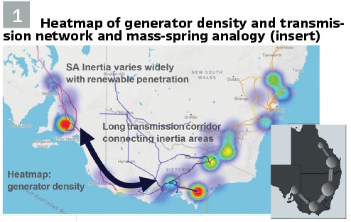
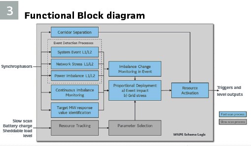
Principles of Operation: The Australian power system has long-distance transmission connecting clusters of load, generation and associated inertia, as illustrated in Figure 1. This can be understood in terms of a mass-spring analogy where the masses are centers of inertia related to centers of generation and load, and springs are the connecting corridors. A disturbance involving loss of generation or load in South Australia leads to a changing frequency as well as a change to the stress in the transmission system, analogous to stretching the spring between the areas. There is a dynamic component to the network stress, as the power exchange and corresponding angle difference will rise, overshoot, oscillate and normally settle to a new steady state. Loss of transmission strength in the connecting corridor e.g. through line or transformer tripping, series capacitor bypass or loss of voltage support is analogous to a weakening of the connecting spring, and can be observed as an increase in angle difference across the corridor. This loss of one or more transmission elements will also produce a transient and settling response that may be stable or unstable.
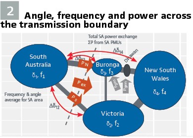
Disturbances to the South Australian region’s power balance or the strength of the interconnecting corridor pose a significant risk of separating South Australia from the rest of the National Electricity Market (NEM). In the event of such a separation, the region must re-balance the net power gain or loss caused by the interruption of the interconnection, as well as address the net loss of generation or load resulting from the initial event. When system inertia is low and the power imbalance is large, the resulting high Rate of Change of Frequency (ROCOF) can lead to further issues, such as distributed generation disconnections, activation of special protection systems, and, in extreme cases, a regional blackout. The SAIT RAS approach addresses these risks by monitoring the angle and frequency of the South Australian center of inertia relative to the angle and frequency at the southern end and the New South Wales end of the interconnection corridor, using synchrophasor measurements. This process is illustrated in Figure 2 and enables the scheme to detect and respond to critical disturbances effectively.
The SAIT RAS scheme comprises three main components. The Event-Driven Component (EDC) control actions are armed based on the pre-contingency power flows to and from South Australia. When a tripping of an interconnector path is detected, the EDC Central Unit sends a signal to the Remedial Control Centre (RCC) to initiate remedial actions. The EDC serves as the primary mechanism for responding to non-credible losses of an AC interconnection. The Response-Driven Component (RDC) logic utilizes time-synchronized wide-area measurements based on synchrophasor technology. Its operation is triggered by the angular separation between South Australia, New South Wales, and Victoria.
The RDC is activated under the following conditions: when the response provided by the EDC is insufficient to stabilize the system or when the event escalates into a complex scenario due to cascading disconnections of generators, loads, and distributed energy resources, as well as the subsequent activation of existing special protection systems within the NEM; when a double circuit trip occurs while the EDC is not armed or out of service, and the triggering criteria for the response-driven path are met; when events result in the severance of the Heywood Interconnector (HIC) or South Australia-New South Wales interconnector (SNI), which are not detected by the EDC; and when multiple generation or load loss events occur, potentially leading to instability in the HIC and/or SNI. Two sets of angular separation thresholds are used in the RDC, and when these thresholds are reached, the RDC sends signals to the RCC to initiate remedial actions.
The RCC plays a critical role in the SAIT RAS scheme by monitoring the availability of loads, generators, and Battery Energy Storage Systems (BESS) using the Supervisory Control and Data Acquisition (SCADA) system. Based on the outputs from the EDC and RDC, the RCC issues trip or control signals to individual loads, generators, or BESS, ensuring a coordinated and effective response to stabilize the system during disturbances.
The synchrophasor measurements used in RDC logic also include power measurements across a boundary cut set for the transmission corridor. The dynamic behavior of angle and frequency in the regions is captured by aggregated multiple synchronized measurements, so that the effect of local dynamics is small providing redundancy for the regional measurements. The key purpose of the scheme is to avoid a separation through re-balancing the region during the disturbance and re-aligning angles to avoid reaching the point of instability or cascading outage.
There are FOUR core criteria used for triggering a re-balancing response:
1. Network stress. Angle and frequency difference for an emerging angle stability event
2. Power imbalance. Generation loss within South Australia that could destabilize the system and/or lead to sustained overload (discriminated from short term swing)
3. System event. Large & fast frequency and/or ROCOF change in response to a disturbance, which is typical for low SA inertia conditions
4. Power Flow: Import or export of huge amount of active power flow from SA in response to a disturbance
The network stress trigger uses angle and frequency difference directly as triggers for a response. It also uses a combination of angle and frequency difference to form a “projected angle difference” trigger variable. Frequency difference is a measure of how rapidly angles are moving and can be used along with the angle difference to identify an estimated angle difference, and therefore accelerate a trigger when the angle difference is large and growing. A network stress measure is useful as a trigger as it is directly related to the angle stability of the system and will pick up cases where the interconnection is weakened, or a large power change causes angle separation, or a combination.
Power imbalance in South Australia is identified using the inter-area power exchange and the ROCOF and inertia within South Australia. The raw inter-area power exchange does not immediately change following a power balance change such as a generation loss. The power exchange shows a swing in power in which the power towards South Australia increases. The power will typically take about a second to swing to its peak overshoot value and then oscillate and return to a new steady state. This dynamic behaviour is defined by the inertia and strength of the interconnection, and the prevailing inter-area dynamics. Therefore, the raw value of power exchange is not an ideal measure of the actual power imbalance when a fast response is required.
Instead, the power imbalance measure uses the ROCOF and inertia in South Australia in combination with raw power exchange to derive an accelerated measure of power imbalance. Referring to Figure 3, the power imbalance of South Australia is given by the raw power exchange plus the power to or from the rotating masses as they decelerate.
The actual power imbalance, which is the gain or loss of net power feeding into the South Australia area is given by:
Pimbal = -Pimport + k.Hsa .RoCoFsa
where:
Pimport is Instantaneous Power import to SA (measured)
Pimbal is the Total Power Imbalance to be identified
Hsa is the effective inertia of South Australia
k is the constant of proportionality to relate ROCOF x inertia to a MW contribution
RoCoFsa is the average rate of change of frequency of the SA centre of inertia
The system event addresses disturbances that give rise to rapid changes in frequency, typically in low inertia scenarios when few synchronous machines are running. With low inertia in the area, a change to the power balance in the area leads to a greater change in ROCOF than would occur in a high inertia condition. A restorative action based on large ROCOF can be triggered before the system reaches a large angle separation and can capture events where the loss of generation may not be excessive, but the low inertia leads to an unusually large effect on the system. The system event also includes triggering for large frequency deviation from nominal, subject to the condition that the disturbance has originated within South Australia.
The active power flow limit for the Heywood Interconnector (HIC) and the South Australia–New South Wales Interconnector (SNI) was considered in the SAIT RAS for triggering. When a significant amount of active power is imported into or exported from South Australia for a certain duration, it can affect the region’s steady-state stability. Based on the instantaneous active power flow in the HIC and SNI corridors, restorative actions can be initiated before the system exceeds its specified operating limits.
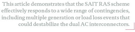
According to the design illustrated in Figure 4, the “SAIT RAS Central Unit,” represented within the dotted region contains the core logic for this wide-area protection scheme. The design also incorporates an additional element for a third level of response (L3), which is based on the Event-Driven Component (EDC). The EDC operates as a fast control loop and requires a dedicated device due to its faster cycle time compared to the RDC logic.
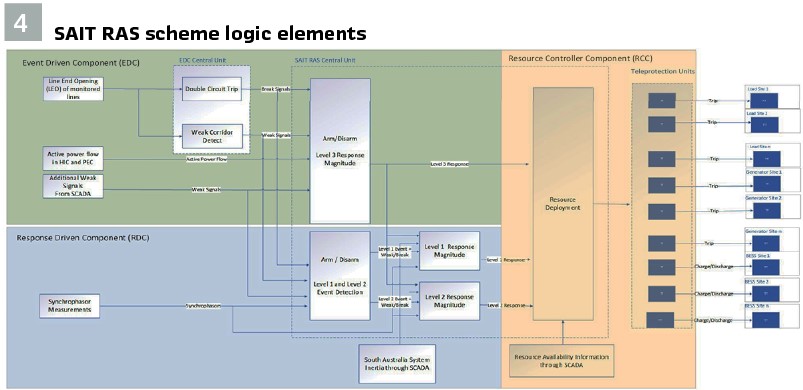
The SAIT RAS scheme employs three distinct trigger levels. The Level 3 response is initiated by the EDC when a double circuit outage is detected. The response is based on pre-contingency flows recorded five seconds before the event (holdover time to be finalized during detailed design) and the strength of the remaining interconnector path. This level triggers the tripping of loads or generators. The Level 1 response is initiated by the RDC when the first set of thresholds is breached, leading to an increase or decrease in the output power of BESS. The Level 2 response is also initiated by the RDC when the second set of thresholds is breached, triggering additional load or generator tripping. This is illustrated from the open loop test result in Figure 5 where the L1 trigger occurs first due to the lower thresholds and if the event continues to worsen (which it will in an open loop test), the L2 event will be triggered which will call on the second stage of response to more aggressively alleviate the condition. The required response for Levels 1 and 2 depends on the total power imbalance within South Australia and the strength of the interconnector path.
The PMU input sections in Figure 4 are designed as reusable components, allowing separation of PMU-related logic from the LEO detection algorithms. This separation ensures scalability and modularity in the scheme, facilitating future expansions or upgrades. The SAIT RAS Central Unit application as shown in Figure 4, is distributed across multiple devices. A set of devices are used for PMU data reception and preprocessing, while another dedicated unit calculates the EDC response, and a second unit determines the RDC response. Finally, the resource available information is handled on a separate device running in an asynchronous manner compared to the other devices. It receives the resource information from the EMS data.
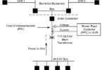
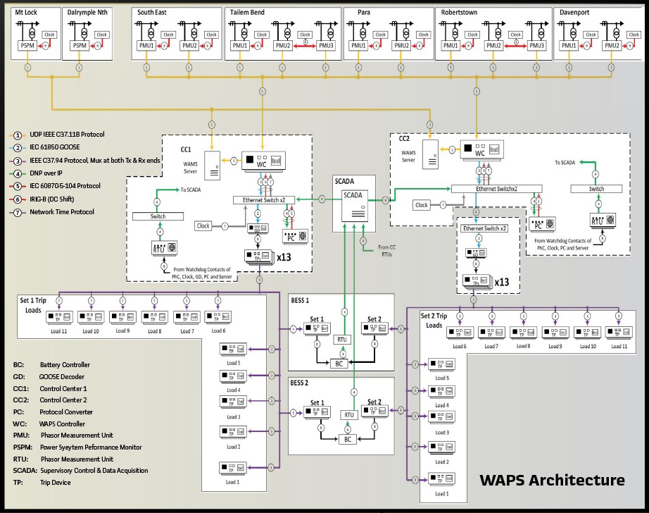
Redundancy: For redundancy, the SAIT RAS Central Unit is independently deployed in two locations, with each deployment receiving data from 28 PMUs in parallel through two physical connections. The architecture showing this configuration from the single interconnector phase is shown on page 46. The PMUs comply with the IEEE C37.118-2011 (rev 2014) standard, meeting the fast response protection class (P-class) requirements, which offer approximately 100ms faster latency compared to the slower measurement class (M-class). UDP is used for data transport instead of TCP to eliminate the latency associated with retransmission. The outputs of the EDC and RDC from the two data centers are logically OR’ed at the controlled resources to ensure reliability.
To enhance resilience, each unit in the SAIT RAS Central Unit is equipped with two network ports connected to two physically independent network switch segments in active-backup mode. One port is active while the other serves as a backup. In the event of a failure in the active network segment, such as a driver, port, cabling, or switch failure, the backup port becomes active within a few hundred milliseconds, ensuring uninterrupted traffic routing. Other critical infrastructure, including the server of WAMS PDC and time servers, also employs the active-backup setup. Each site uses SCADA gateways for communication with the EMS. These components are connected to two independent switch segments to segregate EMS traffic and improve resilience.
Testing: Testing on a wide area scheme can be quite complex due to the number of inputs and outputs involved. The testing procedures however are becoming more standardized through the development and implementation phase. The initial testing involved open-loop testing which is used as part of the design studies to determine trigger types, trigger logic and trigger settings. Large datasets captured from dynamic model simulations are used to play through the scheme from which an automated report can be created showing the results from each test. Given this is part of the design stage, it is necessary to assess the triggering performance using these tests.
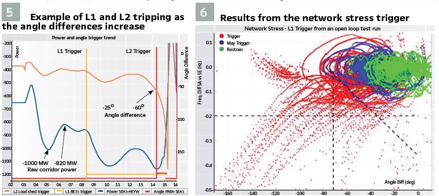
Therefore, such a report would show the time-series data for the different triggering mechanisms, illustrating the thresholds and assessment against the expected outcome. Such testing is automated such that changes to logic or thresholds can be made and tests rerun efficiently. An example of the network stress test results from a test library batch is shown in Figure6 where the results of the full test library can be shown and the cases for which the scheme is expected to operate are marked in different colors. It provides the engineering team with a visual assessment on where the thresholds lie compared to the various cases which are expected to operate. In this case, a case in red must trigger, but cases in green should not, so thresholds must be set such that green cases would not trigger. As these are time-series results, an event shown in red may start off in the same region as a green case, but will then move outside of these regions into the triggering zones as the case progresses. Cases can also be assessed on a case-by-case basis, which is especially critical when fine tuning the scheme.

Once open loop testing has been validated, the system will begin the closed loop testing to validate that the outputs of the scheme will indeed balance the system as required and maintain the system stability. Once closed loop testing has completed, the solution would enter the standard implementation testing stages such as factory and site acceptance tests. Testing System Integrity Protection schemes, or Wide-Area Protection and Control schemes will always require significant testing due to the number of scenarios for which the scheme is expected to operate under.
Trip Signals: GOOSE decoders translate EDC and RDC trip signals into binary signals for controlled resources. The GOOSE decoders are breaker monitoring and control units which have the functionality to receive GOOSE signals, perform fast logic and output signals on physical interfaces. Control units and GOOSE decoders are connected to two independent switch segments to segregate GOOSE traffic. EDC and RDC trip signals are sent as two independent GOOSE messages from separate ports and are logically OR’ed at the GOOSE decoders. Four site-to-site teleprotection connections (C37.94) link the GOOSE decoders at both control sites. This setup ensures that trip signals are relayed between the sites, maintaining functionality even in the event of a GOOSE decoder failure.
The Event Driven Control device receives GOOSE inputs from a network relay located in the same substation. Both components are connected via the same switches as the GOOSE decoders. The network relay sends two independent GOOSE messages that are logically OR’ed by the Event Driven controller. Multicast filtering on the switches ensures proper segregation of GOOSE messages between these devices. To segregate management traffic, the management ports of all devices, including control units, the WAMS, relays, GOOSE decoders, Management PC, and the remote access PC, are connected to an independent switch segment. This configuration ensures secure and efficient handling of traffic.
Biographies:

Sean Norris is a Senior Innovation Application Architect with GE Vernova Grid Automation, based in Edinburgh, UK. Seán has over 11 years’ experience with GE in the field of wide-area control with a particular focus on frequency and transient stability and product development in these areas. He is currently working on the next generation of zonal autonomous control within GE Vernova and is an active member in working groups for System Integrity Protection Schemes and Generator protection and control.

Maman Ahmad Khan is a Lead Engineer at GE Vernova, specialising in Wide Area Monitoring Systems (WAMS) and Wide Area Monitoring, Protection, and Control (WAMPAC). With over six years of experience in both academic and industrial research, he has worked extensively on power system modelling, stability analysis, and protection schemes. His expertise includes developing and validating control strategies for large-scale renewable integration and optimizing system operations.

Douglas Wilson is the Chief Scientist for the WAMPAC product in GE Vernova. He is responsible for innovation and strategic projects in wide area measurement, protection and control. He has worked in the field of power system dynamics and stability since 1998 and was part of the team creating the world first power system damping monitoring system. He is involved in design and implementation of novel wide area control systems worldwide, with a focus on addressing grid stability in the energy transition.

Priyank Shah is a Lead Engineer at GE Vernova, specializing in Wide Area Monitoring Systems (WAMS) and Wide Area Monitoring, Protection, and Control (WAMPAC). His expertise includes power system protection schemes, stability analysis, and advanced simulations using PSS/E and Opal-RT for reliable power system operations. Dr. Shah has received several prestigious awards, recognizing his contributions to the power systems field. He is committed to advancing energy solutions that help achieve zero carbon footprints and optimize grid performance for a more resilient future.

Devinda Perera is a Principal Power Systems Engineer at ElectraNet. He is responsible for delivering on ElectraNet’s planning obligations regarding non-credible contingency events and developing Emergency Control Schemes to address these risks. Devinda has over 10 years of experience in power system modelling and analysis. He is interested in wide-area monitoring and protection and special protection schemes. Devinda holds Bachelor of Science (Engineering) and Doctor of Philosophy degrees from the University of Moratuwa and the University of Wollongong.

Hugo Klingenberg has over 30 years’ experience in the fields of power system planning and analysis, having led engineering teams in consulting, distribution and transmission companies.
At ElectraNet Hugo has managed teams performing the functions of power system planning, estimating, connection assessments and power system capability before taking on the role of Manager Network Transformation. The focus of this role is to be ElectraNet’s key contact to guide the operational transition of the transmission network into a 100% renewables future.