by Walter Schossig, Germany, and Thomas Schossig, OMICRON electronics GmbH, Austria
This is the first article of a series on earth fault detection. The topic started with the introduction of three-phase systems. Three phase AC systems were introduced just prior to the turn of the 20th century when Edison’s initial infatuation with DC systems was redirected toward AC system, initially above all for lighting purposes.
It was not until 1886 when William Stanley developed his commercially practical transformer that the first 4000-foot lighting installation at Great Barrington, Mass. Ushered in the era of AC lighting. Nicola Tesla, a Yugoslav born immigrant entering the US in 1884, disclosed the radical concept of a rotating magnetic field, leading to the first practical induction motor four years later.
One year later, the first long-distance power transmission system for lighting of some 13 miles was placed in operation between Portland and Willamette Falls, Ore., while George Westinghouse introduced the 60 Hz frequency in 1891, which became the standard in the US.
These breathtaking achievements of the electrical pioneering giants came fast and furious with scant indication of the grounding mode being employed. But there is reason to believe that the early three-phase industrial power systems were operated delta-ungrounded for the practical reason that only three power conductors were required to supply the three-phase loads.
Ungrounded systems offered the obvious advantage that no unscheduled service interruption was required at the first incident of a phase-to-ground fault.
Motor windings insulations were particularly vulnerable, and their failure often escalated to extensive motor-core damage, resulting in expensive repairs. The investigations established that the so-called ungrounded system in fact are weak.
On existing ungrounded systems, the physical neutral point being absent, the principal solution was to ground a corner of the delta. As a more effective alternative, a neutral-deriving transformer was used to furnish a neutral point for solid grounding, or occasionally to permit applying a neutral resistor to reduce the ground-fault current to a minimum. In new installations, the simple specification of a delta-wye rather than a delta-delta connection of transformer windings gradually resulted in wye-connected neutral-grounded systems superseding delta systems. For ground-fault protection purposes, the transformer protection specification also required that the neutral of the wye winding be brought out through an isolation bushing. The consequences of grounding the neutral were distinctly different in utility systems than in industrial power systems. That compelled the individual evolution of separate grounding practices.
Here we are going to focus on utility practice. The transmission and distribution systems are generally operated with solidly grounded neutrals, to secure the unique advantages of this mode of operation as well as its distinct surge- and overcurrent protection suitability. The characteristically high ground-fault current magnitudes of solid grounding require overhead static wires and/or buried counterpoises to safely carry about 20 kA of ground current. The early attempts of utility engineers to reduce these ground-fault current magnitudes included experimentation with “Tuned reactor”. Grounding, in which a variable-inductance neutral reactor XL was tuned to the capacitive reactance to ground of the system. On the occurrence of a ground fault the combination of these capacitive and inductive reactances then appeared to the system as tuned parallel circuit of high impedance, limiting the ground fault current to a value approaching 0 A. Also known “as Petersen coil” of “ground-fault neutralizer” this grounding mode gained popularity in Europe.
Even if the neutral point treatment or rather the grounding of the network is insignificant in terms of pure energy transmission, it still has a major influence on the magnitude of the fault current and network overvoltages, danger to people and animals and supply failures.
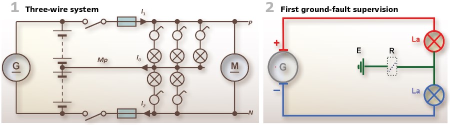
In the block power plants built at the end of the 19th century, direct current transmission with a two-wire network was sufficient. In 1880, the Englishman John Hopkinson introduced the three-wire system. Incandescent lamps for 110 V were connected to the external conductors against the center conductor and motors were connected to the external conductors (Figure 1). Short circuits are isolated by the fuses in the external conductors. Fuses originally installed in the center conductor “Mp” led to voltage increases and were abandoned again.
To detect ground faults, A. Weinhold suggested in 1885 two light bulbs connected in series with the same voltage as the system. The middle between them was grounded. As long as there is no error, the light bulbs shine evenly weakly. If an earth fault occurs on the external conductor, the lamp connected to it will either be weaker or not at all, while the other lamp will shine brighter. In order to achieve an audible signal, a shunt bell or, better yet, a relay can also be looped into the connection to earth. If the fault was in a customer’s home, it was easily remedied by briefly grounding the relevant main line and the increased current caused the house fuse, a lead plug, to melt. The operator found out from the customer in which house the error was to be found. (Figure 2).
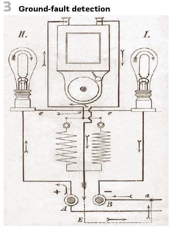
As a practical example, Figure 3 shows the earth fault indicator. As soon as there is a ground fault in the control center with a resistance of only a few ohms, the operator is visually informed by a lamp lighting up that a significant ground fault is present. Now it is important not only to detect significant ground faults, which barely have a few ohms of resistance, but also to have the insulation fault indicated even if its resistance, for example another 1000 or 2000 Ω. For this purpose, a bell device K is switched on in the connecting line from the lamps to earth, which begins to ring at a current of 0.1A and under the condition that the voltage between the two main cables is 100 V. If we ignore the lamp resistance for the time being, this chime is activated at an insulation resistance of 1000 ohms. You can use several branch resistors in parallel with the chime; connecting a branch resistor which has the same resistance as the chime, then the current will pass half through the chime and half through the branch resistor; So, there must be a total of twice the current strength or 1 A if the bell is to be activated.
In this case, if we ignore the resistance of the lamps and the bell, the insulation resistance would have fallen to around 500 ohms. In this way it is possible to inform the machine operator through signals whether the insulation resistance of the cables is 1000, 500, 200, etc. ohms. If the apparatus has indicated the presence of a ground fault, in order to remove it, the operator will of course also need to know the location where this ground fault is located. Finding it in the usual way, when several hundred houses are connected, would be an extremely difficult and time-consuming job. One by one, all the houses would have to be separated from the main lines, and in the house where the earth fault then appeared, the lines would have to be separated from each other again in order to be able to use a galvanoscope to increasingly localize the location and finally be able to find the place at which damage to the insulation has occurred. In order to simplify this time-consuming work, at least in the case of strong earth faults, there is a lead circuit B (Figure 4) in the central station, which on the one hand is connected to earth E and, on the other hand, can be connected to the positive or negative main cable using a switching device.
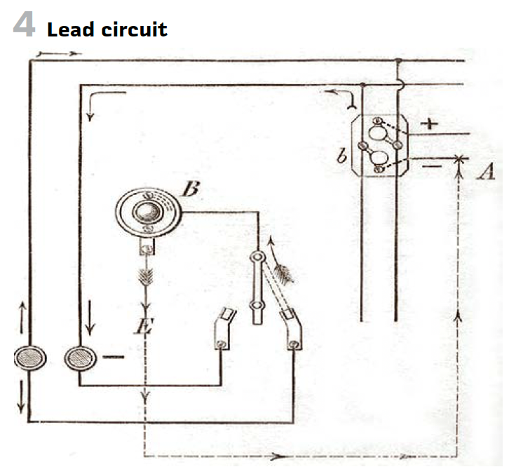
If a ground fault now occurs at point A and the lead plug B is connected to the positive line, the current will pass through the line in the direction indicated by the arrows and cause a direct short circuit, with the lead plug at point b when is weaker than that in B, will melt and the lamps that were connected to the line in question will go out. The consumer, in whose house part of the line is switched off in this way, will of course demand a new lead plug, and this way the operator will find out in which line the insulation damage has occurred and can arrange for the appropriate repair, but this operation is only possible in the rarest of exceptional cases, and may only happen at a time when, such as for example at daybreak, the extinguishing of the lamps will cause the least disturbance.
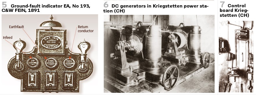
At the International Electrotechnical Exhibition in Frankfurt/M. (DE) in 1891 C&W presented the ground-fault indicator EA. (Figure 5).
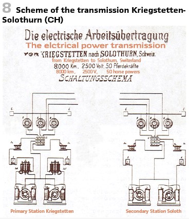
With two machines connected in series (Figure 6), Charles Brown built an 8 km long line for the Oerlikon machine factory in 1866 for an operating voltage of 1250 to 2000V, 15 to 18 A, from Kriegstetten Figure 7 to Solothurn (CH). Figure 8 shows the scheme. E are the earthing plates, B- are the lightning plates, U is the switchover device, Au- is the switch off device, A the Amp meter.
Because the line diameter was 6 mm, an efficiency of 75% was. The insulation condition was checked by simultaneous measurement of current and voltage at the beginning and end of the line. The observers of the measuring instruments in Kriegstetten included Dr. Kopp, assistant at the Federal Physical Laboratory in Zurich. The Solothurn electrical measurements were obtained by the reporter by reading the current intensity during the times 0 to 10 s, 20 to 30 s, etc. and the potential difference during the times 10 to 20 s, 30 to 40 s, etc. Of course, one could also have determined the insulation resistance using a measuring bridge, but the value found in this way would hardly be very reliable. The cable was therefore examined with the working voltage and the results were (See Table 1).
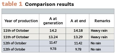
The differences between the two measurements, sometimes positive, sometimes negative, are viewed as observation errors and the insulation of the line was described as perfect in every respect.
The technical limits of direct current transmission were soon recognized. Conflicts over the power system best suited for lighting and power networks, which in America had degenerated into violent feuds between Edison, as the advocate of direct current, and Westinghouse, alternating current, also spread to Europe.
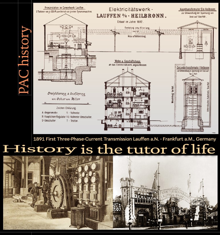
Frankfurt am Main was planning a municipal power supply network around 1890 and therefore examined the advantages and disadvantages of all known power systems but was unable to make a decision. The suggestion was made in expert circles to hold an international electricity exhibition in order to simultaneously get to know the latest technology and compare the different systems with each other.
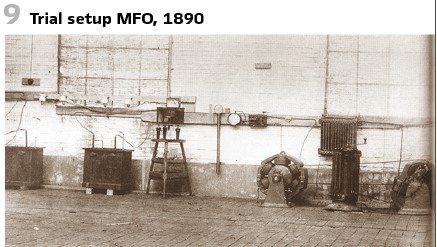
Oskar von Miller was appointed director of the exhibition, and since he was building a hydroelectric power station near Lauffen am Neckar, he came up with the idea of transferring power from there to Frankfurt after the exhibition. This bold plan was met with so many concerns and objections from German authorities and companies that, in particular, Miller contacted the Swiss machine factory Oerlikon, which built a test facility (Figure 9) to test high-voltage transmission. The new idea of this system was to use transformers not only to step down a high generator voltage to a low bulb voltage, but also, conversely, to step up a low generator voltage to a high line voltage. Previously, the generators were directly dimensioned for the line voltage.
The experimental setup from 1890 is shown schematically in Figure 10.
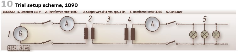
Tests and measurements were carried out on the 10km long test line with voltages of up to 40000 V and no abnormal phenomena emerged, not even when one pole of the high-voltage line was connected to earth. The telephone line, which was attached to the same poles below with staples, was only 30 cm apart and even at 30000 V there was a humming noise when the telephone was in operation, which was only less annoying than the noises that were known from neighboring telegraph lines. This was important because the planned power transmission over 175 km was to follow the railway line along which numerous telegraph lines already ran.
The problem of star point grounding preoccupied the pioneers of electrical power transmission as early as the commissioning of the first electrical power transmission.
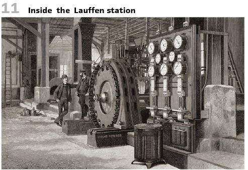
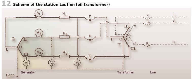
During the first three-phase transmission from Lauffen a.N. to Frankfurt a.M. (see page 70). In 1891 with 15000 V, the star points of the generators and the transformer in Lauffen (Figure 11 and Figure 12) and in Frankfurt a.M. were rigidly grounded. There are n switches on the high-voltage side, but only three fuses F1, F2, F3.
Making a fuse for 10,000 V is not an easy task, but it has been solved by Ferranti and others, and one would have some of the existing forms for Lauffen, but since it is the intention of the two entrepreneurial companies to later work with twice the voltage, it was considered safest to use the fuses like this to interpret that there can be no doubt about their effectiveness even at 20000 or 30000 V.
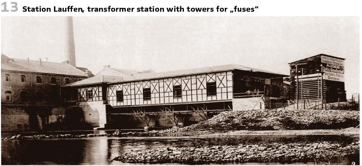
The installation of them on a board inside the station has therefore been abandoned, rather they are installed outside, where they form part of the line. Close to the generator station behind the transformer house (Figure 13), the first two masts were set up just 2.5 m away. In between each conductor was a pair of copper wires with a diameter of only 0.13 mm. In order to achieve their renewal, the poles have been made climbable.
This precaution is necessary because the line in Frankfurt is often short-circuited to force the engineer in Lauffen to shut it down.
For this purpose, in Lauffen and all intermediate railway stations) an angular iron short circuit (Figure 13) is suspended above the 3 wires of the line, which, when lowered by means of a cord, creates a metallic connection between the 3 wires. (Figure 14). Figure 15 shows the presentation of the solution.
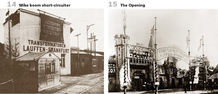
This causes the fuses in barrels to be melted and the operator switches off, then telephones are connected to both ends and the line wires are used to speak between the two ends. The line also had a lightning rod and a lightning cable made of ordinary barbed wire at the top of the mast. The spines were expected to have a special effect. The purpose of grounding the high-voltage windings in Lauffen and Frankfurt am Main was to prevent the voltages between a conductor and earth from becoming greater than the star voltage of the high-voltage windings of the transformers (around 8500 V). Furthermore, if a conductor breaks, it could cause a short circuit and melting the fuse comes. It is said that Dolivo-Dobrowolsky had a wire cut during the acceptance tests during operation and kept the end to show that this could be done without endangering life.
At that time, it was probably also possible to monitor the generator current and automatically switch off the generator in the event of an overcurrent. However, such an automatic operation was seen as too drastic a measure, especially if the malfunction was insignificant and could be eliminated without stopping the machine. It was better to rely on the operator’s ability to react. If one assumes that the connection between the mains star point and earth is a fuse, reserve protection was achieved for the single-pole earth short circuit.
While in America, for example, and in the majority of countries the transformer star point is solidly grounded or via an ohmic resistance, in Germany the star point is insulated. Frankfurt am Main was a notable exception when, at the beginning of the 1890s, a power plant was built along with a cable network for 3 kV single-phase alternating current and a frequency of 45.3 Hz.
Water resistance of 3 Ω limited the earth fault current to around 1000 A and the current-dependent overcurrent timer triggered the oil switch.
info@walter-schossig.de www.walter-schossig.de
thomas.schossig@omicronenergy.com
Biographies:

Walter Schossig (VDE) was born in Arnsdorf (now Czech Republic) in 1941. He studied electrical engineering in Zittau (Germany) and joined a utility in the former Eastern Germany. After the German reunion the utility was renamed as TEAG, Thueringer Energie AG in Erfurt. There he received his master’s degree and worked as a protection engineer until his retirement. He was a member of many study groups and associations. He is an active member of the working group “Medium Voltage Relaying” at the German VDE. He is the author of several papers, guidelines and the book “Netzschutztechnik
[Power System Protection]”. He works on a chronicle about the history of electricity supply, with emphasis on protection and control.
Thomas Schossig (IEEE) received his master’s degree in electrical engineering at the Technical University of Ilmenau (Germany) in 1998. He worked as a project engineer for control systems and as a team leader for protective relaying at VA TECH SAT in Germany from 1998 until 2005.
In 2006 he joined OMICRON as a product manager for substation communication products. He is author of several papers and a member of standardization WGs.