By Thomas J. (TJ) Purcell IV, Dominion Energy Virginia, Josh Wold, Md Arif Khan, and Jared Bestebreur, Schweitzer Engineering Laboratories, Inc., USA
According to the U.S. Energy Information Administration, the U.S. battery storage capacity is expected to have nearly doubled from 2023 to 2024. Inverters play a critical role in integrating these variable renewable energy sources and battery storage systems into the electric grid.
Dominion Energy Virginia has deployed a Wide-Area Monitoring System (WAMS) to help effectively operate the grid as it rapidly changes with renewable integration. This article focuses on detecting oscillations, most of which are caused by inverter-based resources (IBRs). The utility has installed a large number of digital fault recorders (DFRs) with synchrophasor streaming capability across Virginia and North Carolina. These devices monitor hundreds of solar farms, data centers, substations, and distribution centers. They stream voltage and current phasors at 30 messages per second back to servers for storage and analysis. Unlike data captured by supervisory control and data acquisition (SCADA) systems, these synchrophasors have enough resolution to identify oscillations at frequencies up to nearly 15 Hz. With such a large amount of streaming data, it is essential to have software capable of automatic data analysis, easy asset navigation, and user notifications when events occur.
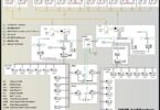
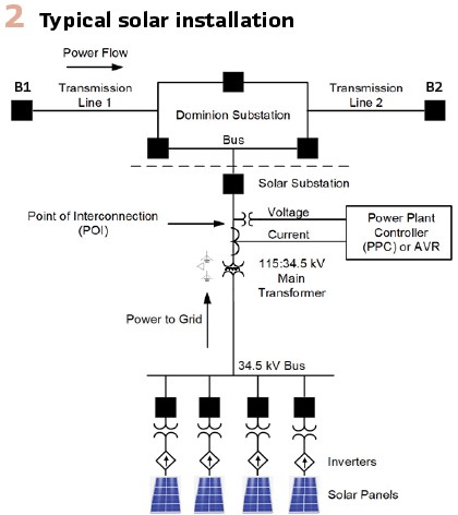
With the increase in integration of IBRs into power grids, oscillations due to controller mistuning or malfunctioning are becoming increasingly prevalent. Controller issues vary widely and can range from problems with individual devices to complex interactions between device-level and plant-level controllers. Consider the transmission subsystem in Figure 2, in which the utility integrates power from a solar site that connects to the transmission network via a three-breaker ring substation. The system goes into a radial configuration when either Breaker B1 or B2 is open and only one end of the network is connected to a source other than the solar site. If B1 and B2 are closed, the configuration is described as networked. The transmission system is considered operating in a normal state when there are a few or no outages across the service territory, and, in most cases, the normal state of the transmission system is a networked configuration.
During nonpeak loads in the spring and fall, various transmission lines and generators are removed from service for maintenance or construction. Switching operations are performed to remove the necessary equipment from service while maintaining a configuration that reliably supplies end users. These switching operations can result in radial configurations, and the utility has observed that these configurations commonly result in oscillatory behavior when an IBR facility is connected radially. These oscillations can serve as critical indicators of underlying issues that demand attention from generation owners.
Traditionally, at the utility, transmission operators detected oscillations by receiving repeated over- and undervoltage alarms or repeated fault recorder triggers. Additionally, the transmission operators were notified by end users or generator owners who observe abnormal electrical behavior. These events were observed only once every few years. The events are complex and require expertise from technicians and engineers from both generation and transmission. Due to the large number of factors involved, understanding and resolving these events can take days.
Since 2021, reports of abnormal events across the utility’s system have increased, due to the increase in IBR-connected generation. The process to analyze these events has been refined and improved to reduce analysis time, pinpoint the source of the oscillation, and resolve the issue in a timely manner. Synchrophasors at each IBR site that feed into an automated oscillation detection tool that is integrated into the WAMS software has been proven to be the most efficient way to detect the issues in near real time. The oscillation detection algorithm monitors voltage magnitude and real and reactive power signals for any oscillatory behavior, estimates the magnitude of oscillations across configurable frequency ranges in real time, and creates alarms when any oscillation magnitude exceeds a threshold. These alarms direct the attention of operators and engineers to problem areas of the grid.
In most cases of abnormal oscillations, the utility has investigated to find the root cause and, when necessary, worked with generation owners toward a permanent resolution. A sample of specific events that have occurred at the utility over the last several years, along with discussion of their cause and resolution, follows.
Power Plant Controller (PPC) Oscillation, Winter 2021
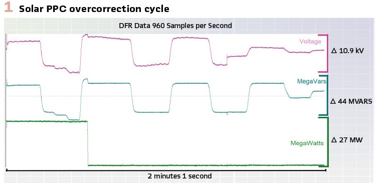
A localized voltage and reactive power oscillation at a solar facility occurs after the site’s connection to the transmission system switches from a network to a radial configuration. A short oscillation immediately follows the switching but decays quickly. However, the PPC is not properly tuned for the weaker radial configuration, and it starts a cycle of overcorrection, alternating between increasing and decreasing reactive power, causing the voltage magnitude to oscillate.
The oscillatory behavior decays over a period of seven minutes and eventually returns to normal.
Figure 1 shows a portion of the overcorrection cycle.
Following this event, the PPC is retuned to reduce the gain of the voltage control loop. The new settings are tested by repeating the network-to-radial configuration change, and the site responds as desired. No further tuning is required.
Load Oscillation, Summer 2022
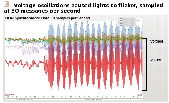
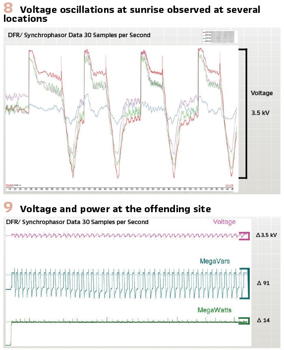
A localized voltage oscillation causes lights to flicker in the affected area. End users call the utility to alert them of the problem. The oscillation persists for a total of nearly 2 hours. Figure 3 shows a representative sample of the voltage oscillations at several locations. The beating behavior in the voltages is due to the undersampling of the oscillation by the phasor measurement units (PMUs); the oscillation frequency is very close to the 30-sample-per-second PMU Nyquist rate of 15 Hz. The undersampling causes some loss of fidelity, but the oscillations are still clearly visible and can be detected by the automated scheme.
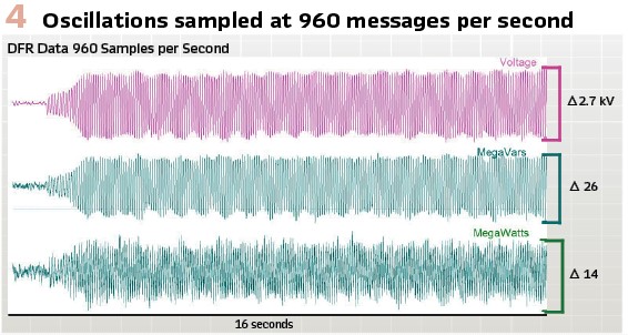
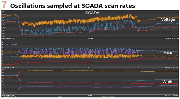
Figure 4 shows the voltage and power quantities at the point-of-interconnection of the offending site. The higher-rate data in the figure show the oscillations with the most fidelity. Figure 7 shows the same signals, and other signals nearby, captured by the SCADA system. The low scan rates result in the magnitude of the oscillatory behavior being drastically underestimated. Because of this, SCADA data are unsuitable for capturing these oscillations, and PMU data are required.
Approximately 1 hour before the oscillations begin, a nearby synchronous generator is taken offline. The oscillations begin when a second synchronous generator is also taken offline. The oscillations persist until capacitor banks and flexible ac transmission system (FACTS) devices are switched into service. Further investigation reveals that improper settings on the uninterruptible power supply at the industrial load site cause the problem and are modified. After the settings change, lower-level oscillations are still present.
Solar Sunrise and Sunset Oscillations, Fall 2022
A localized voltage oscillation at a solar facility begins at sunrise when the site power output begins ramping up. The oscillations are detected by the automated detection scheme in the WAMS system. A comprehensive review of the data from the site shows oscillations each day at sunrise and sunset, though the rms magnitude is below the configured threshold. Further, data from fall 2020 show that similar oscillations have been occurring. Seven other solar sites show similar behavior. Figure 5 shows the voltage and reactive power oscillations at several sites.
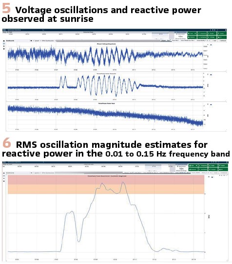
Figure 6 shows rms magnitude estimates for reactive power oscillations produced by the automatic detection scheme. The offending site crosses the alarm threshold, and the alarm alerts engineers to the problem. Figure 5 and Figure 6 are directly from the user interface for the software running the detection scheme. Voltage oscillation monitoring (results not shown) also detects the problem and creates an additional alarm.
No switching events or suspicious system configuration are found to correlate with the events. The oscillations persist until solar irradiance is high enough for the sites to meet their requested real power output. Discussions with various inverter manufacturers indicate that they are familiar with the issue, and they suggest that settings changes resolve it.
Low-Power Oscillations, Fall 2023
A localized voltage oscillation occurs at a solar facility when an inverter’s power requested from the PPC is curtailed to 0 MW at full irradiance. The oscillatory behavior is detected by the automated scheme. Figure 8 and Figure. 9 show the observed voltage and power oscillations.
An investigation by the site owner reveals that the oscillation is caused by the PPC entering a cycle of turning an inverter on and off. When the total power request for the plant necessitates turning one or more of the individual inverters off, these inverters consume a small amount of power, causing the aggregate plant power to drop below the requested aggregate power plus the deadband. This, in turn, causes the PPC to turn the inverters back on.
The minimum achievable power from these inverters then causes the aggregate power to move above the set point, and the cycle repeats itself. After reviewing and understanding the standby power consumption of the individual inverters, the PPCs’ minimum power output is adjusted, and subsequent tests verify that the problem is resolved.
Multisite PPC Oscillations, Winter 2024
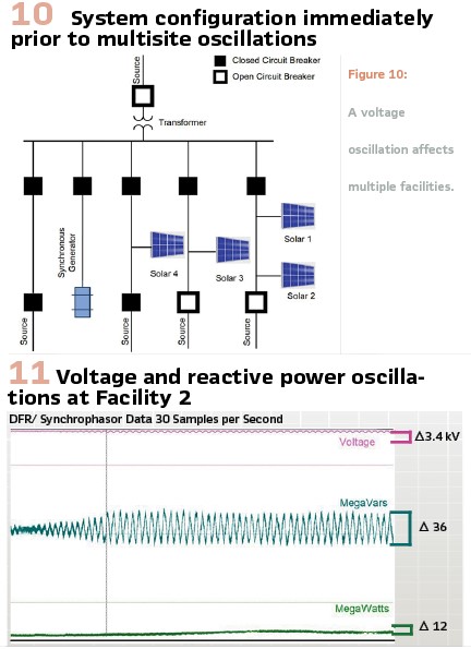
A voltage oscillation affects multiple facilities. The automated detection system creates alarms at several facilities, and end users call the utility and report flickering lights. It is caused by various system reconfigurations from network-to-radial and controller interactions between multiple generation sites. The configuration of the affected area is shown in Figure 10.
No switching operations or system activities take place in the immediate time before the oscillations begin; however, a synchronous generator is just taken offline.
Synchrophasor data show that the voltage and reactive power changes are largest at Solar Facilities 1 and 2, with Solar Facility 3 showing large, intermittent voltage swings. From the previous day, Solar Facility 2 shows large voltage swings, but because Solar Facility 3 does not (it is in a network configuration), Solar Facility 2 is initially identified as the source of the problem. Changing the PPC at Solar Facility 2 from the voltage control mode to the power factor control mode eliminates the oscillations.
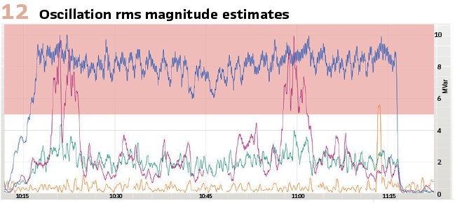
Figure 11 shows voltage and power data from Solar Facility 2. Figure 12 shows the rms magnitude estimates for many sites. The affected sites show clearly larger estimates and differ significantly from the ambient level, making them easy to detect.
Further investigation shows that the PPCs at Solar Facilities 1 and 2 simultaneously attempt to correct the voltage, which exaggerates the overall correction. A review of all solar facilities in the area shows that each PPC has been tuned independently when its associated transmission connection is in a network configuration.

During the largest swings, six solar facilities’ PPCs and one synchronous generator’s voltage regulator actively respond to the changing voltage levels. Because of this, it is difficult to pinpoint a single source of the oscillation. Many facilities are affected, and each PPC behaves differently.
Ultimately, the oscillation is caused by the interaction between all of the controllers because they are all tuned without the consideration of nearby controllers.
Conclusions
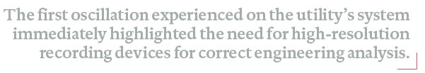
The first oscillation experienced on the utility’s system immediately highlighted the need for high-resolution recording devices for correct engineering analysis. Without it, no conclusions could have been identified.
Sensing Equipment: provides the key evidence necessary to detect and locate oscillation events. A high-density system of synchrophasor and continuous digital recording devices is critical to identify the source of these types of events, analyze their impact on other facilities, and work towards a resolution. At Dominion Energy, this is achieved using the DFRs as multifunction devices, high-resolution recorders, fault locators, and synchrophasor streaming devices. High-resolution evidence that pinpoints a particular facility is absolutely critical when approaching owners with requests to retroactively make changes. The DFR provides this direct evidence in various forms.
Synchrophasor systems, ranging from primary voltage- and current-sensing devices to the final storage and visualization media, should include devices with a wide-frequency response that allows oscillation detection at low levels. Sensing, detecting, and resolving issues at lower levels help avoid future problems.
SCADA data do not accurately represent the dynamic nature of voltage and reactive power due to its low scan rate. This makes it difficult to understand the source of the problem. DFRs and DFR synchrophasors are the only devices on the utility’s system that can record with the high-resolution data needed for an accurate analysis.
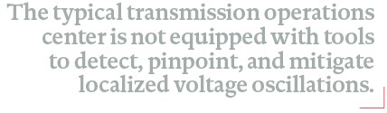
Localized Voltage Oscillations: The typical transmission operations center is not equipped with tools to detect, pinpoint, and mitigate localized voltage oscillations. Without these tools, oscillations are not discovered until they are sufficiently severe enough that they affect the low-resolution SCADA data or end users complain.
However, localized voltage oscillations can be clearly identified by synchrophasors (streaming from the fault recorder), and they especially stand out in reactive power signals at each generator and IBR. Ideal system monitoring includes voltage oscillation detection at select sites throughout the system and reactive power oscillation detection at all IBR and synchronous generators.
As the number of IBRs and synchronous generators increases, it gets more difficult to pinpoint the location of an oscillation.
FACTS devices help reduce the voltage impact of oscillations; however, their reactive power output should be monitored to ensure an oscillation is not simply masked by the support device.
IBR site monitoring should start during or at least immediately after site commissioning and be compared to baseline values to quickly identify and resolve any abnormalities emanating from the site. The longer an issue is outstanding, the more difficult it is to request that the site owner make changes to correct it.
PPCs are tuned during normal system configuration and are not changed unless requested. Such requests are infrequent or nonexistent. The controllers typically do not have gain scheduling or a similar capability to retune when the system configuration is changed (e.g., if a line switches from network to radial) or if another plant is constructed in close electrical proximity. One PPC manufacturer explained that their equipment does not have separate settings for different configurations, so it would have to be reprogrammed every time the line configuration changes. The manufacturer suggested that the utility turn down the voltage response gain to delay responsiveness but ensure stability.
This is a stopgap solution, which will not work in the long term, because each time the system changes topology or another IBR is added in the area, the controller will need to be retuned. Retuning involves technicians and engineers being onsite and hooking up specialized test equipment.
PPC settings and configurations are the same for each solar IBR site, and dynamic modeling is not performed on a site-by-site basis.
Certain IBR solar sites have trouble controlling power output at low values (<2 MW).
PPC and inverter settings at sites near each other can conflict, leading to localized voltage issues under abnormal network conditions.
Synchrophasors: Storing all synchrophasor data indefinitely makes postevent analysis extremely efficient. This includes having an interface to quickly compare quantities across the system.
Monitoring each data stream allows for maximum coverage. Providing alarms when the current is interrupted improves system reliability and helps quickly resolve complicated issues.
Synchrophasor oscillation detection software provides the ability to monitor IBR and other transmission-connected devices continuously, as opposed to commission and spot checks. This allows each site owner the autonomy to complete upgrades and work as needed without negatively impacting local grid voltage.
Prior to synchrophasor oscillation detection software being deployed, the utility required engineers to manually look at each part of the system for voltage issues. Issues are invisible until they become a large enough problem to be detected with SCADA or until sensing equipment is deployed.
Manually reviewing just one point in time may prevent reviewing the time when the system is in its weakest state and most susceptible to oscillations. The oscillation detection tool presented in this article makes engineers’ work more efficient and aids in fast problem identification and resolution.
Biographies:

Thomas J Purcell (TJ) is a Consulting Engineer at Dominion Energy Virginia, where he works in System Protection Automation and Analysis, focusing on transmission, distribution, and generation event analysis, as well as fault recorder deployment and maintenance. Other areas of interest include power quality, synchrophasors and Inverter Based Resource Performance Monitoring. He holds an undergraduate degree in Electrical Engineering from Virginia Tech, a master’s degree in Systems Engineering from Old Dominion University, and is a Licensed Professional Engineer in Virginia.

Josh Wold received BS degrees in electrical engineering and mathematics from Montana Technological University and a PhD in electrical engineering from Montana State University. He was a hardware engineer at Schweitzer Engineering Laboratories, Inc. (SEL), from 2009 to 2011, and then a professor of electrical engineering at Montana Tech from 2015 to 2021. Since 2021, he has simultaneously worked as a power engineer at SEL and adjunct professor at Montana Tech. He is a licensed professional engineer in Montana.

Md Arif Khan is a senior power engineer with Schweitzer Engineering Laboratories (SEL), Inc., and is responsible for development of new power system metering, monitoring, operations, and control technologies. He is a senior member of IEEE and a member of Tau Beta Pi Honor society. He was the recipient of KUET University Gold Medal in 2010, President’s Award in Rocky Mountain Bioengineering Symposium in 2014, and University Wyoming (UW) Engineering Excellence Fellowship from 2014 to 2018. He earned a B.S. degree in ECE from KUET, and a M.S. and Ph.D. in electrical engineering from UW.

Jared Bestebreur holds a Bachelor of Science in electrical engineering from Washington State University. He is currently a senior engineering manager at Schweitzer Engineering Laboratories, Inc. (SEL) and is responsible for synchrophasor and relay event analysis software products. He has supported the implementation of wide-area monitoring systems around the world. He is also an active member in the North American SynchroPhasor Initiative (NASPI) community.