by Kenneth E. Martin, Electric Power Group, USA

Early real-time applications were primarily geographical system displays showing voltages and power flows that focused on the operational state. These have evolved with applications that:
- Detect and locate sources of oscillations
- Measure system strength and inertia with limit alarms
- Monitor cut-plane phase angles
- Detect disturbances, providing location and alerts
There have been efforts to both keep phasor systems and SCADA independent and to integrate them together. Generally, SCADA has better coverage of control status (switches, breakers, etc.) and voltage/power measurements. Synchrophasors cover system dynamics much better. Combining systems reduces the number of PMU installations required to get system coverage. It also simplifies displays and monitoring procedures. Keeping them separate enables using them for redundancy and allowing system operation with either one without the other. The use of Linear State Estimation (LSE) with phasor systems enables better coverage and higher reliability, so observability with phasor data only is approaching that of SCADA at some utilities. Both systems offer advantages in operation and control of the power grid.
Observability of system dynamics has been the key contribution of phasor measurement systems. As grids have moved from hierarchical management and large synchronous generators to distributed generation and loads with networked transmission and a large contribution of renewables, measurements that capture the resulting complex flow patterns and higher speed dynamics are essential. Synchrophasors have been the key to jumping this hurdle. However, phasor measurement systems are a new technology that required both consistency in measurement and comprehensive communications to be usable and reliable. Support of the technology through standards and guides has provided the requirements and guidance that was needed. The standards and guides developed by the IEEE have been instrumental to this development, by creating the crucial understanding and interoperability. These standards are the focus of this article.
Synchrophasor Standards development
IEEE standard 1344-1995 “IEEE Standard for Synchrophasors for Power Systems” was the first synchrophasor standard. Completed in 1995, it specified synchronization to UTC time, time accuracy, and waveform sampling requirements. It included a simple communication system. Since there was little synchrophasor implementation at that time, the standard did not include measurement validation.
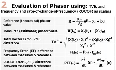
The succeeding standard, C37.118-2005 contained both measurement validation and a communication protocol. The measurement accuracy was determined by Total Vector Error (TVE), where the phasor was compared with the theoretical phasor as a complex number (Figure 2). This method incorporates both magnitude and phase thereby requiring only a single number as the error limit. This standard only validated steady state measurement, where the measurement of magnitude and phase angle were not changing. This standard also developed the data exchange more fully, into a messaging system that could transparently transfer data from the PMU to the PDC as well as PDC to other devices.
To promote compatibility with IEC standards, the C37.118 standard was split into two standards in 2008. C37.118.1 included the previous standard’s provision for synchrophasor measurement. It was further extended to cover phasor measurement during dynamic signal changes. It was also extended to cover the measurement of frequency and rate-of-change-of-frequency (ROCOF) under the same steady-state and dynamic conditions. This standard was completed in 2011 and then amended to adjust some limits in 2014. It was then further improved by a joint IEC/IEEE working group and completed in 2018 as the joint IEC/IEEE Standard 60255-118-1.
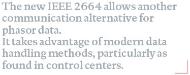
The companion standard, IEEE C37.118.2, contained the communication provisions formerly found in C37.118. This standard made minimal changes from the previous standard to support current systems and was published in 2011. This standard was recently revised and published in 2024. Backward compatibility was supported, so the newer versions can work seamlessly with the older versions.
Synchrophasor standard IEC/IEEE 60255-118-1 ed1.0 “Measuring relays and protection equipment – Part 118-1: Synchrophasor for power systems – Measurements.”
60255-118-1, the current measurement standard, is essentially the same as IEEE C37.118.1. Some of the testing was simplified and the requirement descriptions improved. The format was also changed to agree with IEC procedures.
This standard gives complete mathematical definitions for synchrophasors valid for any operating case (in previous standards, the phasor was defined for steady state only). It also defines F & ROCOF dynamically, the same as previously defined in synchrophasor systems, though this definition may differ from other interpretations.
This standard specifies required reporting rates, the frequency that phasor data estimates are transmitted, but only requires that a PMU be certified at a given rate. Specified rates are 10-25-50 and 10-12-15-30-60 for 50 and 60 Hz systems respectively.
Two classes of performance are defined: M and P classes. The difference is that filtering is required for M class to meet anti-alias provisions. P class does not have filtering requirements so can have a faster response. The class measuring differences are carried through all the requirements.
Steady-state accuracy tests cover magnitude, phase angle, F and ROCOF over ranges of frequency and magnitude. For example, frequency ranges are basically ±2 Hz and ±5 Hz from nominal for P and M classes respectively. Steady-state accuracy is 1% TVE and .005 Hz for phasors and F response. Most requirements have adjustments for reporting rate. Steady state tests also include protection from interfering signals. Both classes have to reject harmonics, though M class is tested at 10% harmonic level and P class is tested at 1%. M class is also required to reject all signals that are above the Nyquist frequency for the given reporting rate.
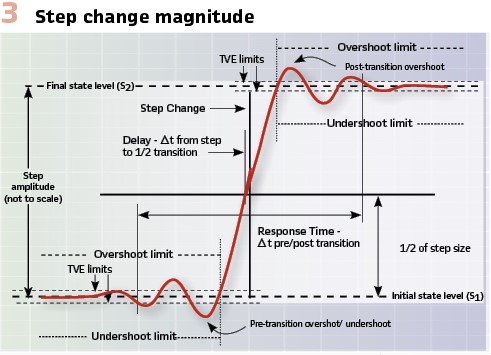
Dynamic requirement tests include bandwidth, response time, measurement tracking, and reporting latency. Bandwidth measurement compares the output with the input over changing frequency. For this test, the input power signal is modulated in phase and amplitude. These tests confirm a 3 dB measurement bandwidth up to 5 Hz or 1/5 of the reporting rate (M Class), though many PMUs have bandwidth approaching the Nyquist frequency. A step of frequency or phase is used to confirm response time, delay, and overshoot (Figure 3). Response time is limited to 7 reports, delay to ¼ report, and overshoot to 10% (M Class). Measurement tracking is assessed by applying a ramp in system frequency. With a 1 Hz/s ramp, both classes are required to maintain accuracy within 1% TVE. Reporting latency observes how quickly the measurement is sent from the PMU, an important factor for real-time control. M Class is allowed a delay of 7 reporting intervals while P Class is limited to 2 intervals. The limit examples given here are for the phasor measurement; F and ROCOF are also evaluated under these same test conditions and have similar but appropriate limits.
Six annexes provide supplemental information on timetagging, mathematical formulations, PMU testing, the reference signals used in limit evaluation, the changes needed for sample value systems, environmental effects, extended range testing, and generator angle measurement.
Synchrophasor standard C37.118.2-2024 “IEEE Standard for Synchrophasor Data Transfer for Power Systems”
C37.118.2-2011 was based on the data communication portion of C37.118-2005. At that time, it was assumed users would be migrating to the IEC 61850 protocol for phasor communication, so the focus for C37.118.2 was to keep backward compatibility and provide needed changes for existing systems. The changes were primarily improvements in STATUS indications, flexible naming, and an extensible configuration frame. However the standard has proven useful and popular among users, so an extensive revision was initiated in 2018 and completed in 2024. This revision adds a number of optional features as well as supporting the combined use with the earlier versions of the standard.
The standard actually defines a messaging system rather than a communication system. This allows using any communication system to carry the messages. It uses a client-server approach where the client contacts the server to establish the connection and request data, then controls the flow. The original standards defined: data, configuration, and header messages from the data source (server) and commands from the data receiver (client). Commands were limited to data flow control. This last revision adds the ability to send remote configuration commands for naming and data configuration, and also adds an error response message to resolve communication problems. The revision also adds data quality options and clarifies use of several of the other indicators and flags. The basic protocol and communications are otherwise unchanged.
The data frame contains the real-time data measured or calculated by the PMU/PDC. The message includes an identification header, message length, the ID of the message stream (connection), a time stamp, information flags on the data status and timing, and, the ‘data’ (Figure 4). The ‘data’ includes phasors (in rectangular or polar format), frequency, rate of change of frequency, and analog and digital quantities. All data may be in integer or floating point format. The status flag indicates data validity, time sync, PMU error conditions and special data considerations.
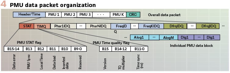
The PMU time quality flag provides an estimate of the measurement time accuracy. These flags are the same as the original status flags in the standard that have been expanded to provide more clarity. They apply to the whole PMU data block. Now an optional 2 byte flag can be included with each phasor, frequency or ROCOF measurement that apply to the individual measurement only. This allows using all data in the frame but the degraded value(s). These flags allow users to decide if the data can be used with an intended application and if the results are trustworthy. As with previous standard revisions, the data frame may contain the data from a single PMU or several PMUs. This allows data from many PMUs to be correlated to a particular time stamp and transmitted as an overall synchronized data frame.
The configuration frames transmit information required to parse and utilize the data. They identify the sending device by name and STREAM_ID. They name and provide scaling for all signals. They give the data types, sizes, and number of entries as needed for parsing the message. They also provide information about the PMU such as location, type, class, and related data.
In this latest revision (version 3), there is a “capability” frame which provides a report of all the data the PMU is capable of providing and a ”stream configuration frame” which provides the information of the current stream. The former replaces the previous “CFG-1” frame and the latter replaces the “CFG-2” and “CFG-3” frames. These new frames follow the “CFG-3” frame format and features but with added flags and information. As in CFG-3, names are a variable length field whose length is indicated by an 8-bit count that is the first byte. This field can then range from 1 (only count byte with 0 bytes of name) to 256 (count byte plus 255 bytes of name). This saves space where there could be a lot of names for unused signals and can be longer when the user wants long names.
Two new configuration options are provided as well. The first is the rename signals frame. This is a subset of the configuration frame which includes new names to be assigned to the PMU and signals. This is intended for setting up a new PMU. The second is the configure stream frame. It identifies which signals will be included and their configuration information such as scaling, and the overall PMU configuration. These frames allow the PMU to be remotely initialized and configured.
The PMU IDCODE was originally included to identify the PMU that was sending data. When multiple streams over networks became used, this ID was also used to identify the stream. As this led to confusion, the new standard has a separate PMU_ID and STREAM_ID for those purposes. This should not require any changes in existing systems but can add flexibility where needed. The command frame is sent by the client to the PMU/PDC (server) to start or stop transmission, request configuration information or send historical data. The command can also be used to send PMU specific actions or settings. A lot of command indications are user definable.
In previous versions of this standard, the PMU only sent messages in response to commands. Now there is an error-response message that can be sent when the server needs to notify the client of an error, such as an invalid message, or bad character. Also a new discrete event data frame can be sent when triggered by an event. This frame will report the actual event time which might be different than the stream timing. The list of digital values is reported in this data frame.

Another new feature is the ability to request old data. This could be data from a historical record or recent reports that were corrupted or lost. Some PMUs may not keep a store of data and can reply to a request that they don’t have data. The data request is made by command and uses the same time protocol used by the streaming data.
Eleven annexes provide useful supplementary information including version 2 requirements, implementation information, and operation of a system that includes devices using different versions of the protocol.
Communication standard IEEE 2664-2024 “IEEE Standard for Streaming Telemetry Transport Protocol”
The new IEEE Standard 2664 introduces the Streaming Telemetry Transport Protocol (STTP), a standard that has been developed over the last decade to address specific issues with existing phasor measurement system protocols. The shortcomings of C37.118 include:
- System configuration is done externally from the communication protocol using equipment vendor tools. This requires extra training and maintenance and is difficult to do remotely
- Data transfer focuses on data blocks defined by the PMU, so it is difficult separating out specific measurements
- Message size control is left to the underlying protocol, which results in data loss due to fragmentation for larger messages
- Security and compression are left to the underlying wire-line protocol
STTP adopts a publish-subscribe architecture where a publisher provides data to authorized subscribers. The subscriber initiates a connection with a request identifying the desired data items using a simple list of identifiers or selection with SQL-adjacent query methods. Once a subscriber is confirmed to meet the authorization requirements, the publisher will begin streaming the requested data items. By focusing on individual measurements, rather than entire data blocks, STTP reduces the overhead of sending unneeded data. Each measurement is commonly represented by real-number values, such as voltage magnitude, voltage phase angle, frequency, real power, etc., but can also be a block of bytes. Each measurement is packaged with an identifier, a data quality indicator, a time stamp, and the value itself (Figure 5).
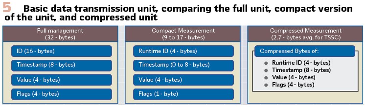
This approach fragments the data stream so that each measurement value at each instant of time has its own small packet which reduces loss by fragmentation and network delays caused by re-transmission. Although this structure can initially add overhead – because many small messages replace fewer large ones—the protocol mitigates this with options to reduce the sizes of identifiers and timestamps, as well as by employing an advanced compression algorithm. Phasor measurements typically exhibit slow-changing values (e.g., voltage or frequency), which allows the compression algorithm to efficiently eliminate repeated bits, reducing the communication burden to below that of other streaming protocols (Figure 5).
In terms of communication layers, STTP is written with the Internet Protocol (IP) in mind, though its design does not preclude operation over other suitable wire-based protocols. The subscriber first connects via a TCP/IP channel, used for command-and-control messages, and then negotiates data subscriptions. These subscriptions can deliver real-time data, historical data, or metadata, and may be used either with the existing TCP command channel or a separate channel, including UDP if appropriate. Publication parameters—such as data rate, communication type, content, and other operational details—are all established through negotiation, making STTP a highly flexible option for many forms of time-series data.
STTP uses an 8-byte unsigned integer to track time, starting from January 1 of year 0 CE (AD), with each count representing 100 ns. This approach, popularized by Microsoft in its timekeeping applications, ensures timestamps remain valid through the year 9999 CE. In situations requiring even higher precision (such as high-speed event recordings or traveling wave analysis), STTP includes mechanisms to store additional precision through offsets. Conversely, if the full precision is unnecessary, the timestamp size can be reduced to save bandwidth.
Triggered bursts of high-speed data are also supported, allowing STTP to send quick bursts of high-rate measurements – such as during a fault – without continuously streaming at that rate. In this configuration, the subscription can remain dormant under normal conditions and automatically switch to higher transmission rates when an event occurs. This flexible subscription model eliminates the need to record data locally and upload it later, thereby making crucial event data available in near-real time instead of being downloaded with a scheduled FTP poll.
The standard includes six annexes with details on compression, filtering, data flags, recommended API approaches, and representation options for metadata.
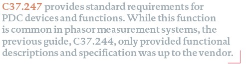
Synchrophasor standard IEEE 37.247-2019 “IEEE Standard for Phasor Data Concentrators for Power Systems”
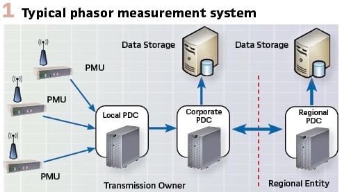
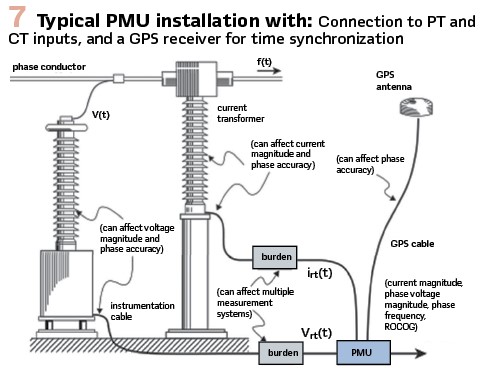
A Phasor Data Concentrator (PDC) is a function or device that receives streaming phasor measurement data and combines it together for distribution to other systems. Phasor measurements are estimated at a precise time and become particularly useful when combined together as a time-synchronized snapshot. The phase angle measurement is based on time, and comparisons between measurements are only valid when time synchronized. The PDC also manages the communication links, performs data checking, manages output data streams, and can perform a number of other data management functions. The main purpose of the standard is designation of certain essential and basic functions that a PDC must provide. This standard takes the place of the previous guide, C37.244-2014, which described the PDC and its related functions.
Functionally the PDC is a node in a phasor measurement system as shown in Figure 1. There may be a number of PDCs in a system, with each one combining data streams from several points. Usually the system forms a hierarchy, but there may be bi-directional data exchanges as well.
The required PDC functions are:
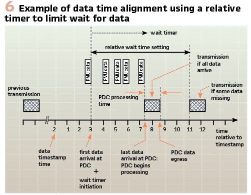
- Time alignment of incoming data including the ability to set wait times. (Since the data will arrive at different times due to processing and communication variation, the PDC must wait a certain time to allow all data for a particular time to arrive – Figure 6.)
- Data forwarding where a single input data stream is sent out without any delay except what the user may impose with data conversions
- Communication interfaces for both input and output fulfilling both client and server functions
- Format and coordinate conversion, such as integer/floating-point or polar/rectangular
- Reporting rate conversion by down-sampling or up-sampling with methods left to the vendor to specify
- Phase angle adjustment with user specified angle adjustments to account for system variations
- System monitoring logs showing operational issues in human readable form
Within each of these categories are detailed operational descriptions for functions like local timestamp assignment (sort-by-arrival) and absent data assignment in output data. The ability to modify data format including coordinate changes, phase angle adjustments, and output data rates as well as change signal names is required for all output functions. The PDC vendor is left to choose which functional methodology they support in some cases, such as using an absolute or relative data loss timer or which protocols are supported for input and output. The standard also specifies Performance requirements which include:
- Maximum processing time for a minimum number of inputs
- Data processing accuracy (covering data format and coordinate conversion specifically)
- Operational robustness which is specified as recovery from an adverse data condition or a system restart
The conditions for performance verification are described in some detail, particularly the robustness requirement. Test procedures are not given as requirements, though Annex B proposes tests to determine compliance with the standard for both functional and performance requirements.
The standard includes 7 Annexes that cover the overall phasor measurement system, testing, special consideration for the C37.118 protocol and details on wait time and latency.
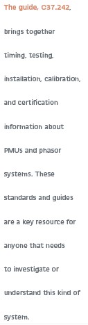
Synchrophasor guide C37.242-2021 “IEEE Guide for Synchronization, Calibration, Testing, and Installation of Phasor Measurement Units (PMUs) for Power System Protection and Control”
The first version of this guide, C37.242-2013, was a combination of individual guides that covered synchronization, calibration, testing and installation of PMUs. It was written as a series of mini-guides based on the available information. This revision of the guide simplifies and reorganizes the material as well as adding the most current updates. It also adds guidance for field calibration and maintenance.
The synchronization section provides an overview of timing sources for PMUs. PMUs require a time source capable of providing continuous time synchronization within at least 5 µs, and preferably within 0.5 µs. Satellite based navigation systems (GPS, GLONASS, Galileo, etc.) are the most available and economical, though communication system based PTP (IEEE 1588) may become competitive in the near future. The guide discusses the important factors and the advantages and disadvantages of each method and system.
Accuracy characterization includes both the PMU and all the devices that feed it including CT, PT, cabling, and timing. Newer sensing devices which provide voltage and current sample values will also effect the calibration. Rather than providing tables and graphs that may be dated, this section now provides methodology and references for evaluating the overall calibration of the measurement system.
The installation, commissioning, and maintenance section provides background on all aspects of these processes (see Figure 7). A number of PMU types are available, and the user can choose one that best matches access to V & I signals, timing input, and data output. Signal input needs to be scaled so the phasor value provides the needed resolution and accuracy at the normal signal level with an allowance for overloads. The timing input can be by direct GNSS or a time code such as IRIG-B or PTP. In the case of GNSS, antenna location is critical for good signal reception and isolation from interference. Communication for data output needs to fit within the available systems at the substation considering both bandwidth and reliability. Cyber security is an important factor that should be included, particularly at key substations.
A completed PMU installation needs to be checked for accuracy and comparability. A PMU will normally be type tested or even calibrated in a lab. The field installation primarily verifies correct connection, calibration, and signal identification. In-station calibration checking with local measurements as well as comparison with other measurements reported at the control centers can provide the needed installation validation. A final close monitor check of the communication link over a few days’ time can reveal communication problems that may not show up until later. A final documentation program will help with problem resolution and system maintenance.
The PMU testing section summarizes the different types of tests including conformance with measurement and communication standards, interoperability, factor acceptance, and field commissioning. It introduces the IEEE Test Suite Specification (TSS) that describes in detail how to test PMUs for conformance with the IEC/IEEE 60255-118-1 standard. This is the defining document used for the IEEE conformance certification program.
For certification, testing equipment needs a 10:1 uncertainty ratio relative to the performance limits. This requires production of test signals with 0.1 % magnitude accuracy with better than 1 s timing synchronization. For the various tests specified in the standard, this requires highly tuned test equipment usually only available in a test lab.
Field testing and commissioning can be done with less precision as it is primarily focused on confirming operation and finding if there are equipment failures. The guide does not provide conformance testing details; these are found in the TSS.
Five annexes provide additional details about measurement data quality, the impact of primary sensors (PT, CT, etc.) on measurement accuracy, installation design and validation, and extensive PMU response plots based on the tests required by the standard.
The first synchrophasor standard was ahead of its time in 1995 but paved the way for orderly development of the technology. C37.118-2005 used early system development as a guide to standardize practical methods and sound principles for measurement validation and effective communications.
Biography:

Kenneth Martin is a principal engineer with the Electric Power Group (EPG). He has over 45 years’ experience in the electric utility industry, first at the Bonneville Power Administration (BPA) in communication, precise timing, instrumentation, and testing. He started working with synchrophasor measurement with the first PMUs in 1987 and conducted the first PMU lab tests. He developed the phasor measurement system at BPA including building the first phasor data concentrator and supported similar developments at many utilities. Mr. Martin chaired the development of the IEEE C37.118 Synchrophasor standard series from the 2005 original, through the 2014 amendment and then convened IEC JWG1 that developed the IEC-IEEE 60255-118-1 standard. He was a lead for developing the TR 90-5 for IEC 61850, He chaired IEEE WG P10 that developed the synchrophasor communication standard, IEEE 2664. Mr. Martin is a Fellow of the IEEE and a registered Professional Engineer. He has authored or co-authored more than 90 papers and articles. He has received awards from IEEE, IEC, and BPA for his technical contributions.