by Alexander Apostolov, PAC World, Los Angeles, USA
The past few decades have been a time of digital transformation that has profoundly reshaped our lives, industries, and societies. As part of this digital revolution, the electric power industry has undergone its own significant transformation, with protection, automation, and control (PAC) leading the change.
The rise of Wide Area Monitoring, Protection, and Control (WAMPAC) systems represents another significant advancement. By utilizing synchronized measurements from Phasor Measurement Units (PMU) across the grid, these systems provide a comprehensive view of power system dynamics, enabling more sophisticated protection schemes and improved situational awareness for grid operators. Communication protocols have evolved to support this new digital ecosystem. The IEC 61850 standard has enabled interoperability between devices from different manufacturers, enabling the creation of integrated substation PAC systems. This integration leads to more efficient operations, reduced maintenance costs, and improved system reliability.
Since the IEC 61850 standard is the cornerstone technology for the digital transformation of electric power systems it is necessary to have a look at how synchronized measurements can be integrated in digital substations and WAMPAC systems based on the standard. To do that we need first to look into what synchrophasors are and analyze the relevant modeling principles and communication services in IEC 61850.
The Concept of Phasor Measurement
Synchrophasors, or synchronized phasor measurements, are time-synchronized data that represent electrical waveforms (voltage and current) in power systems. They are measured using Phasor Measurement Units (PMU), which provide precise real-time data about the grid’s operational state.
A phasor is a mathematical representation of an electrical signal’s sinusoidal waveform, capturing both its magnitude and phase angle. The key feature of synchrophasors is that they are synchronized to an absolute time reference, typically provided by Global Positioning System (GPS) signals. This allows measurements from different locations to be directly compared in real time.
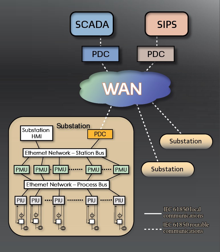
The initial use of synchrophasors was for wide area monitoring when PMUs are installed at all important locations of the network to be observed. The measured quantities are transferred over fast communication links to a monitoring center, where the data from the connected PMUs are collected, aligned, archived and provided to the SCADA or other applications. (see Figure 1).
Classical protective relays perform the protection of single elements of a power system, such as generators, transformers, lines or busbars. For the protection of such objects locally measured values are sufficient in most cases. The response times of such devices are typically in the range of one cycle.
SCADA systems, however, have system wide view of the power system, but due to limited data rates this view is relatively static. The data from the PMUs enable the transition to WAMPAC applications to obtain a dynamic and more accurate view of the grid.
The IEEE C37.118 Standard
The IEEE C37.118 standard is typically used for measuring synchrophasors in electric power systems. It defines UTC as time reference, rate of measurement, co-sine as phase reference, TVE (Total Vector Error) for accuracy metrics and a communication model (format of telegrams).
The standard does not specify speed of measurement, accuracy under transient conditions, hardware / software of the devices and measurement algorithms.
The specifications allow a simple processing of the synchrophasors from different measuring systems, in real-time as well as off-line.
In 2011, as a result of decisions to harmonize IEEE and IEC standards development, the original standard was split in two standards: C37.118.1-2011 – IEEE Standard for Synchrophasor Measurements for Power Systems and C37.118.2-2011 – IEEE Standard for Synchrophasor Data Transfer for Power Systems.
C37.118.1-2011 defines synchrophasors, frequency, and rate of change of frequency (ROCOF) measurement under all operating conditions. It specifies methods for evaluating these measurements and requirements for compliance with the standard under both steady-state and dynamic conditions. Time tag and synchronization requirements are included. Performance requirements are confirmed with a reference model, provided in detail. This document defines a phasor measurement unit (PMU), which can be a stand-alone physical unit or a functional unit within another physical device.
This standard for the first time introduces two performance classes. As the letter indicates, the P class is intended for protection types of applications requiring fast response and does not require explicit filtering. M class is intended for applications which could be adversely affected by aliased signals but do not require the fastest reporting speed, thus the M class requires anti-alias filtering.
All standard compliance requirements are specified by performance class. The standard requires that if a supplier provides both P and M class performance in a device, these shall be user selectable.
IEEE C37.118.1 does not specify hardware, software, or a method for computing phasors, frequency or ROCOF.
The second new standard C37.118.2-2011 specifies a method for real-time exchange of synchrophasor measurement data between power system equipment. It specifies messaging that can be used with any suitable communication protocol for real-time communication between PMU, phasor data concentrators (PDC) and other applications. It defines message types, contents and use. Data types and formats are specified. A typical measurement system is described. Communication options and requirements are described in annexes. The standard defines the formats for frames sent out from the PMU (data, configuration and header) and for command frames sent to the PMU.
Mappings to serial communication and to TCP/UDP are specified.
The data frames contain:
- Synchrophasors of the voltages and/or currents (phase or sequence components)
- Frequency and frequency change
- Further analog and digital values
The configuration and header frames transmit identifiers, format specifications, and conversion factors for the values transmitted in the data frames. The operation of the PMU can be controlled by sending command frames to it, i.e. to request the sending of configuration and header frames or to disable/enable the sending of data frames.
IEC 61850 90-5
Another document that specifies synchrophasor communications is IEC 61850 Part 90-5: Use of IEC 61850 to transmit synchrophasor information according to IEEE C37.118. It provides a framework for transmitting synchrophasor information according to IEEE C37.118 standards within the IEC 61850 ecosystem. This integration enables advanced monitoring, protection, and control capabilities for modern power systems by allowing seamless communication between Phasor Measurement Units (PMUs), Phasor Data Concentrators (PDCs), Wide Area Monitoring Protection and Control (WAMPAC) systems, and control center applications.
The document outlines how synchrophasor data, traditionally communicated via IEEE C37.118 protocol, can be transported using IEC 61850-8-1 GOOSE and IEC 61850-9-2 SV packets over UDP multicast. This approach enhances compatibility across power systems while maintaining compliance with IEC 61850 concepts.
Several key applications are highlighted throughout the document. Synchro-check applications ensure phase angles are properly aligned before breaker closure, preventing equipment damage. Adaptive relaying uses real-time data to dynamically adjust protection settings based on actual grid conditions. Out-of-step protection monitors phase angles and frequencies across substations to detect desynchronization that could lead to outages or equipment damage.
Situational awareness represents a crucial application area, with control centers using synchrophasor data to generate alarms and visualizations that provide operators with real-time insights into grid stability and power flows. State estimation combines synchrophasor and SCADA data to create comprehensive grid models that enhance monitoring accuracy and security assessment efficiency. The document also emphasizes the importance of archiving synchrophasor data for retrospective analysis of past incidents.
The modeling approach within IEC 61850 is detailed, explaining how logical nodes and logical devices represent PMU and PDC components in a hierarchical structure. This structure accommodates both substation-level configurations and regional models that aggregate data from multiple sources.
Communication requirements receive significant attention, with UDP identified as the preferred protocol due to its low latency and ability to handle frequent data streams. The document addresses challenges related to latency, jitter, and packet loss, providing strategies for redundancy and synchronization with different requirements for various applications.
Security is thoroughly covered through a robust model using cryptographic techniques. Key Distribution Centers (KDCs) maintain data confidentiality and integrity, while encryption and authentication protect against unauthorized access or tampering.
The transition from IEEE C37.118 to IEC 61850 includes mapping strategies that ensure compatibility with existing systems while leveraging enhanced capabilities. Extensions supporting IPv6 and advanced data transmission methods are discussed alongside practical deployment examples at substation and wide-area levels.
Engineering considerations include the use of Substation Configuration Language (SCL) files to streamline system design and integration, simplifying the engineering process and ensuring interoperability.
Object modeling principles in IEC 61850
The modeling of a complex multifunctional protection IED is possible only when there is good understanding of the problem domain. At the same time, we should keep in mind that the models apply only to the communication’s visible aspects of the IED.
The functions in relatively simple IED, such as most of the process interface devices, are fairly easy to understand and group together in order to build the object model. That is not the case for the more complex devices like an advanced process interface IED. The modeling of such devices from different vendors that are part of distributed functions requires the definition of basic elements that can function by themselves or communicate with each other.
The basic functional elements defined in IEC 61850 are the Logical Nodes. A Logical Node is “the smallest part of a function that exchanges data.” It is an object that is defined by its data and methods. When instantiated, it becomes a Logical Node Object. Multiple instances of different logical nodes become components of different protection, control, monitoring and other functions in a substation automation system. They are used to represent individual steps or zones in a protection function and are the building blocks of the IEC 61850 model. A process interface IED has a functional hierarchy that needs to be modeled according to the definitions of the IEC 61850 model. In most cases it contains some form of a digitization function, but there are examples of process interface IEDs that may also include a wide range of protection and non-protection functions with high level of complexity.
The different functions can be further divided into a functional hierarchy depending on the type of device we are modeling. Each function can be divided into sub-functions that represent groupings of related functional elements.

An IEC 61850 server (Figure 2) is a device that implements the IEC 61850 communication standard and contains a data model representing all types of substation equipment. The server provides real-time data access and control capabilities to client devices on the network using Abstract Communication Service Interface (ACSI) services. It also supports peer-to-peer communications between multiple IEDs for the implementation of different PAC schemes.
A server can contain one to many IEC 61850 logical devices representing the physical IED or its functions. Each logical device consists of one or multiple logical nodes that are grouped together due to related data and functionality, providing an abstract representation of the physical device capabilities.
Logical nodes group data objects, control blocks, status information, measurements and records using a defined naming convention. Common logical node types include LLN0 which provides overall status information and supports control at different levels of the functional hierarchy. Examples of logical nodes representing functional elements are XCBR that models circuit breakers, TCTR for digitizing current signals, MMXU for electrical measurements, and many others tailored to specific applications. Logical nodes enable interoperable representation of device functionality in substation PAC systems.
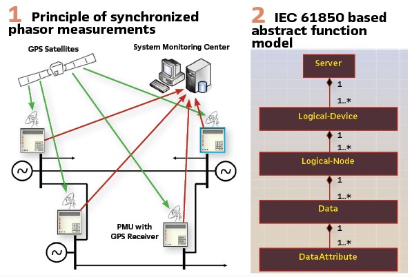
Based on the modeling principles described above we can say that the PMU can be specified as a logical device in the hierarchical model, and it will contain one to many logical nodes MMXU or MSQI that calculate the required by the application synchrophasors.
The PMU is a function within an IED which is responsible for the calculation and publishing of synchrophasor measurements as defined in IEEE C37.118.
These calculations are based on sampled values produced by the analog input module within the IED containing the PMU function or based on streaming sampled values produced by one or more merging units in the substation that the IED containing the PMU function is subscribing to.
If the PMU is publishing phase currents and voltages, one or more instances of MMXU will be used. If the PMU is publishing sequence currents and voltages, one or more instances of MSQI will be used.
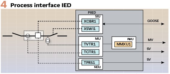
The PMU logical device can be located in different physical devices searches in the process interface device shown in Figure 3. For the calculation of the synchrophasors it is subscribing to the streaming sample values of the current and voltage signals published by the merging units in the digital substation. However, the PMU can also be located in a multifunctional protection IED that subscribes to the sample values published over the process bus in the substation.
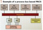
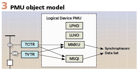
A Process Interface IED (PIIED) is the most complex interface device (Figure 4) that combines the functionality of a PIU with synchrophasor measurements or local protection, control and/or other non-interface functions.
Synchrophasor data model
In IEC 61850 MMXU is a logical node used for measuring electrical parameters such as voltage, current, power, frequency, and phase angle. It can serve as a standardized interface for processing sampled values from merging units and sharing the calculated measurement data with other logical nodes in the same or other IEDs.
For synchrophasor applications, MMXU plays a crucial role in computing phasor magnitudes and phase angles from the raw sampled values. It processes the real-time voltage and current data, applies phasor estimation algorithms, and provides the synchronized phasor values.
Since MMXU can be used to calculate different values of the currents and voltages, IEC 61850 uses a data object ClcMth (CalcMethodKind) calculation method kind to describe what the output value is. This is an enumerated value and the following numbers are used to indicate the output value is a synchrophasor:
11: P-CLASS – All analogue values (i.e., all common attributes ‘i’ and ‘f’) meet the sampling and filtering characteristics specified in IEEE C37.118.1 for PCLASS
12: M-CLASS – All analogue values (i.e., all common attributes ‘i’ and ‘f’) meet the sampling and filtering characteristics specified in IEEE C37.118.1 for MCLASS
The data objects used to represent synchrophasors are:
- PhV Phase to ground (line) voltages
- A Phase to ground/phase to neutral three phase current
- Both of them are from the WYE class which contains the following attributes:
- phsA: Value of phase A
- phsB: Value of phase B
- phsC: Value of phase C
- neut: Value of the measured phase neutral
All of these values are of type CMV – a common data class used to represent complex measured values which have magnitude and angle attributes.
Synchrophasors transmission
Once the synchrophasors are calculated they need to be transmitted within the digital substation or between different locations in the electric power grid. This transmission can be done differently using IEC 61850. depending on the application. Considering the traditional streaming transmission of synchrophasors we can use the sampled values communications mechanism defined in the standard.
In an IEC 61850 digital substation, Sampled Values (SV) are transmitted over the process bus according to the IEC 61850-9-2 standard. This allows digitized measurements from MUs to be shared with IEDs using an Ethernet-based communication network.
In most existing installations these signals are converted into digital Sampled Values with a sampling rate of typically 80 samples per cycle for 50/60 Hz systems according to IEC 61850-9-2 Light Edition (LE).
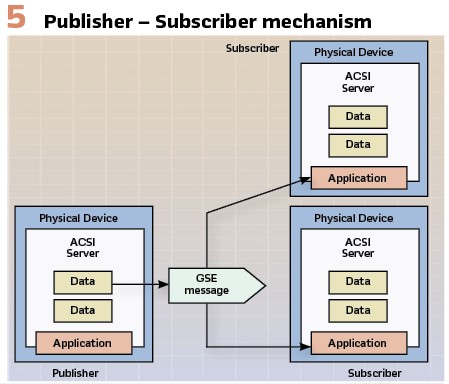
Once digitized, the Merging Unit publishes the Sampled Values in a multicast format over the process bus using a Publisher-Subscriber model see (Figure 5).
The SV messages contain time-synchronized voltage and current samples along with a time stamp. IEDs subscribe to these messages and use the data for real-time protection, control, and other functions. (see Figure 6).
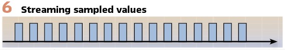
Each Sampled Value message consists of an Application Protocol Data Unit (APDU) that includes a dataset identifier, sample counter, time stamp, and sampled voltage and current values for each phase. An APDU may contain one to many samples. The message is transmitted as an Ethernet frame using MAC multicast.
The same communication mechanism can be used for the transmission of synchrophasors however with different sampling rates. To support this the standard has modified the sampling rate definition by supporting 3 different options defined by the date object sampling mode SmpMod:
- Samples Per Period 0
- Samples Per Second 1
- Seconds Per Sample 2
Each of these three options can be used for the transmission of synchrophasors depending on the calculation frequency and the type of synchrophasors being published by the PMU.
The integer value of the data object sampling rate SmpRate is then interpreted by the application based on the selected value for the sampling mode.
In the case of transmission of synchrophasors the members of the data set are the magnitude and angle attributes of the current and voltage complex measured values. (see Figure 7).
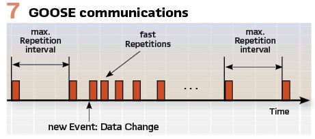
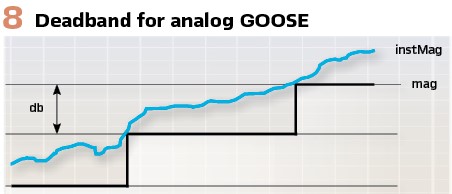
While the traditional approach is the use of the streaming sample values mechanism described above it is also possible to use an event driven method based on the so-called Analog GOOSE (see Figure 8).
This is based on the fact that the members of the GOOSE data sets do not need to be only binary or integers but also can be analog values. In this case an analog event that requires the transmission of a message with a new state number is defined by a dead band (db) for the magnitude or angle values of the synchrophasors complex measured values.
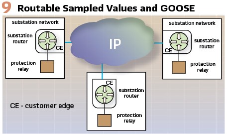
Since many of the use cases for synchrophasors applications require their transmission outside of the substation IEC 61850 – 90-5 defined Routable Sampled Values (RSV) communication over IP-based networks (see Figure 9) rather than being restricted to a local Ethernet process bus. Unlike conventional SV, which uses Ethernet multicast at the MAC layer, RSV enables data to be routed across different network segments, making it possible to share real-time measurements between substations, control centers or other remote locations.
RSV is designed to operate over the User Datagram Protocol (UDP), which is a transport protocol that supports fast and efficient data transmission. UDP is used because it allows for low-latency, high-speed communication without the overhead of connection-oriented protocols like TCP. Since RSV messages contain time-sensitive sampled values, UDP ensures that data is delivered quickly, even if some packets are lost, as real-time applications can tolerate minor data losses more than delays caused by retransmissions.
Biography:

Dr. Alexander Apostolov received his MS degree in Electrical Engineering, MS in Applied Mathematics and Ph.D. from the Technical University in Sofia, Bulgaria. He is Principal Engineer for OMICRON electronics in Los Angeles, CA. He is an IEEE Fellow and Member of the PSRC and PSCC. He is past Chairman of the Relay Communications Subcommittee, serves on many IEEE PES WGs. He is a member of IEC TC57 WGs 10, 17, 18, 19, Convenor of CIGRE WG B5.86 and member of several other CIGRE B5 WGs. He is a Distinguished Member of CIGRE. He holds 4 patents and has authored and presented more than 500 technical papers. He is an IEEE Distinguished Lecturer and Adjunct Professor at the Department of Electrical Engineering, Cape Peninsula University of Technology, Cape Town, S. Africa. He is Editor-in-Chief of PAC World Magazine.